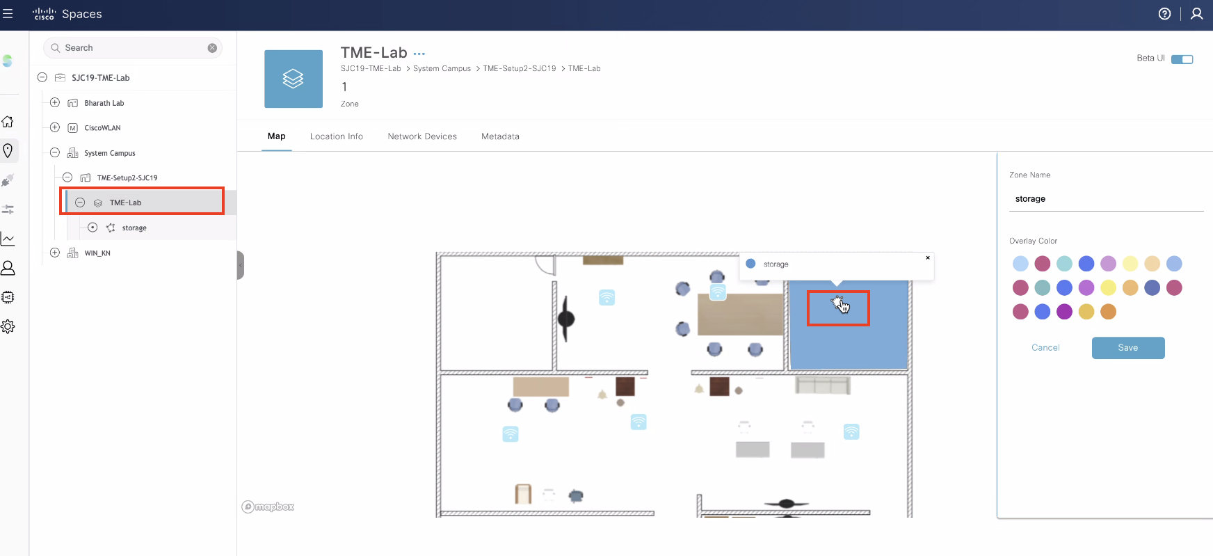
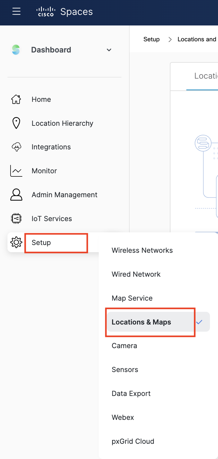
Login to the Cisco Spaces dashboard click the Menu icon ![]() and Navigate to Setup > Locations & Maps
and Navigate to Setup > Locations & Maps
If you do not have any locations in your location hierarchy then your view under Setup > Locations & Maps will look like the following image.
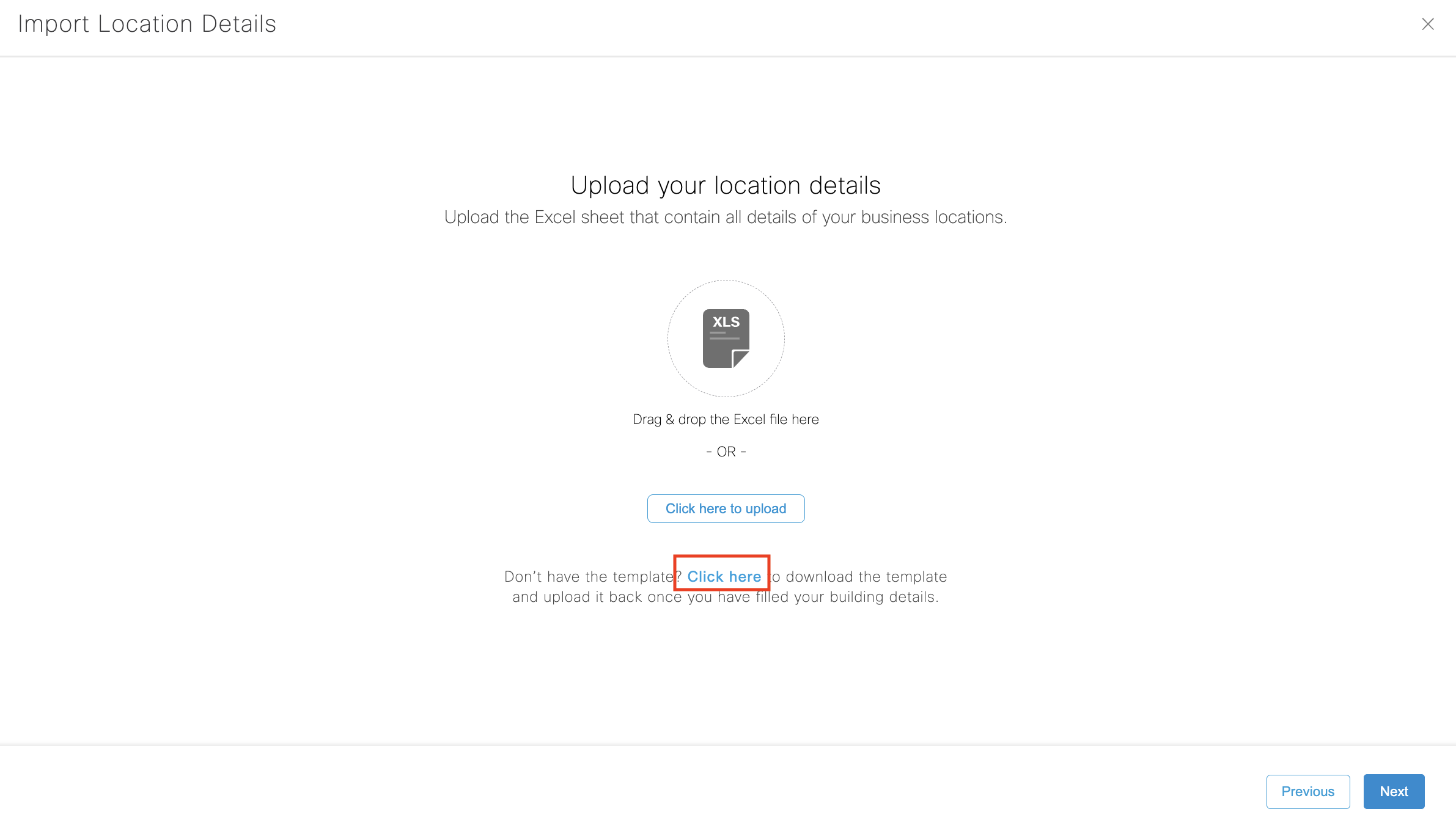
Select ‘Click here’ to download the Excel template that will be used to build the new hierarchy
Fill in the location info in the Excel template – refer to the image below for details on the Excel template items.

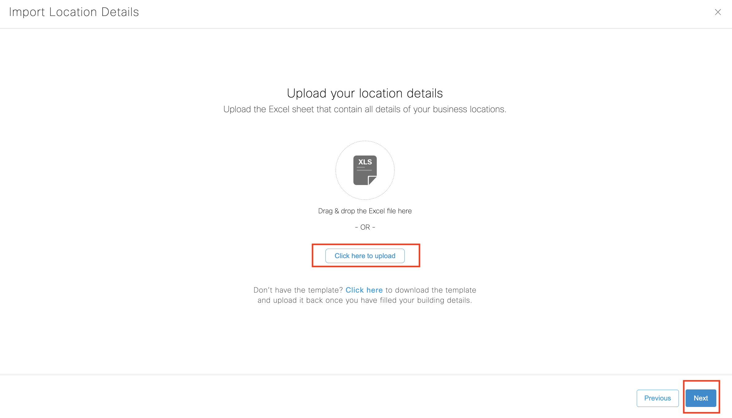
Once the Excel sheet is ready with the required data Click on ‘Click here to upload’ to upload the file and Select “Next”
Cross-check if the columns imported match the mapped data. Tag the columns with appropriate data based on your Excel sheet wherever needed.

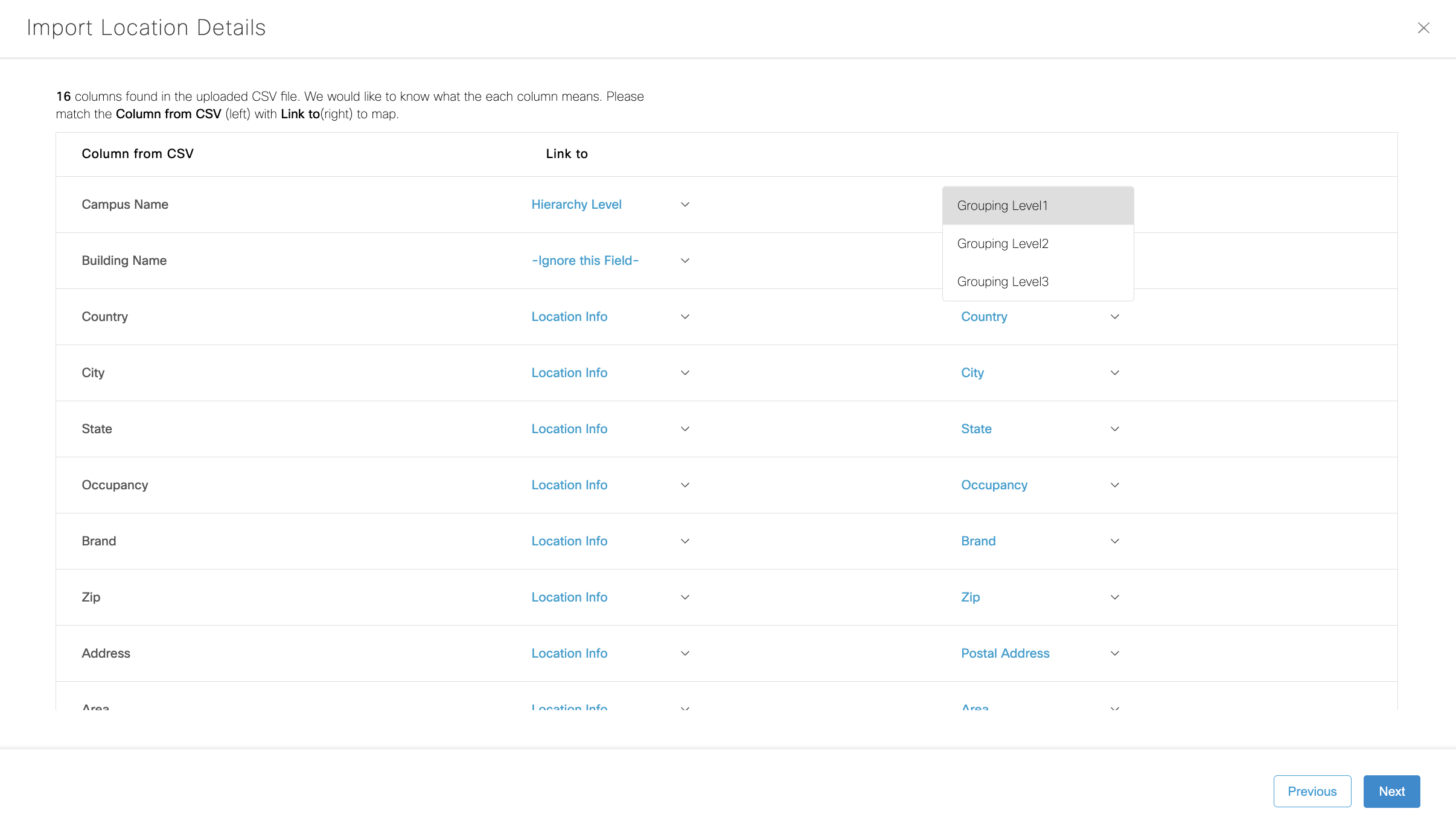
Once the data is mapped correctly Click “Next” to proceed
Since it is a new location we shall keep it as ‘create as new’ and click “Next”
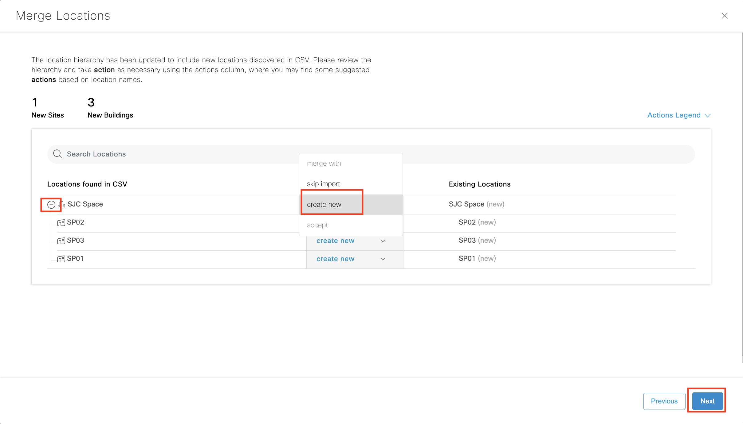
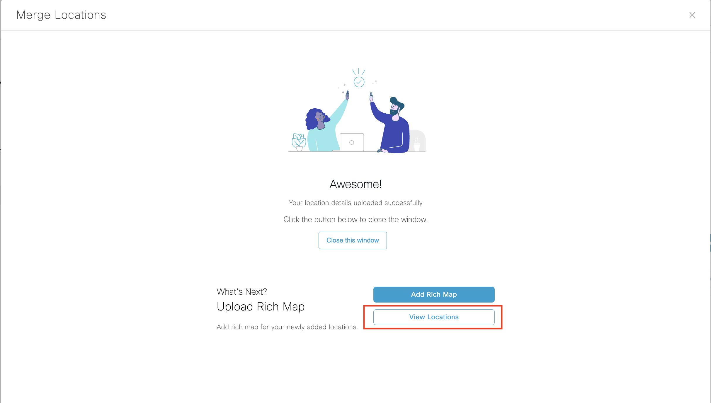
Once the location details have been added successfully Select “View Locations”
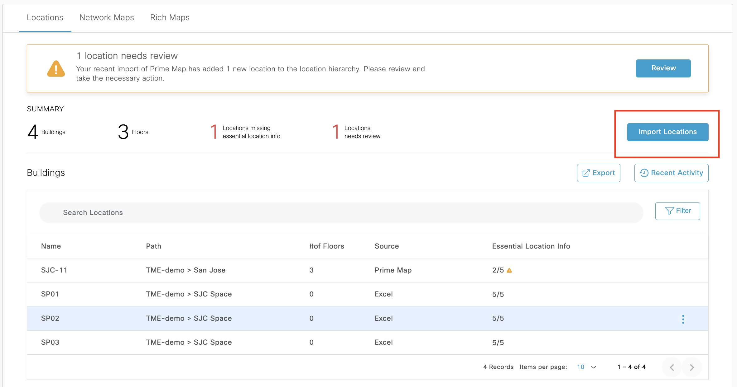
Now that the Excel sheet is imported, proceed to sync Network Hierarchy by clicking on “Import Locations”
Choose to Import one or more ways to onboard Location Hierarchy from the options below:
Import Location from Webex
Import Locations from Meraki
Import Locations from Catalyst Center (formerly DNA Center)
Import Locations Manually
If you do have an existing location Hierarchy You can view it under Setup > Locations & Maps
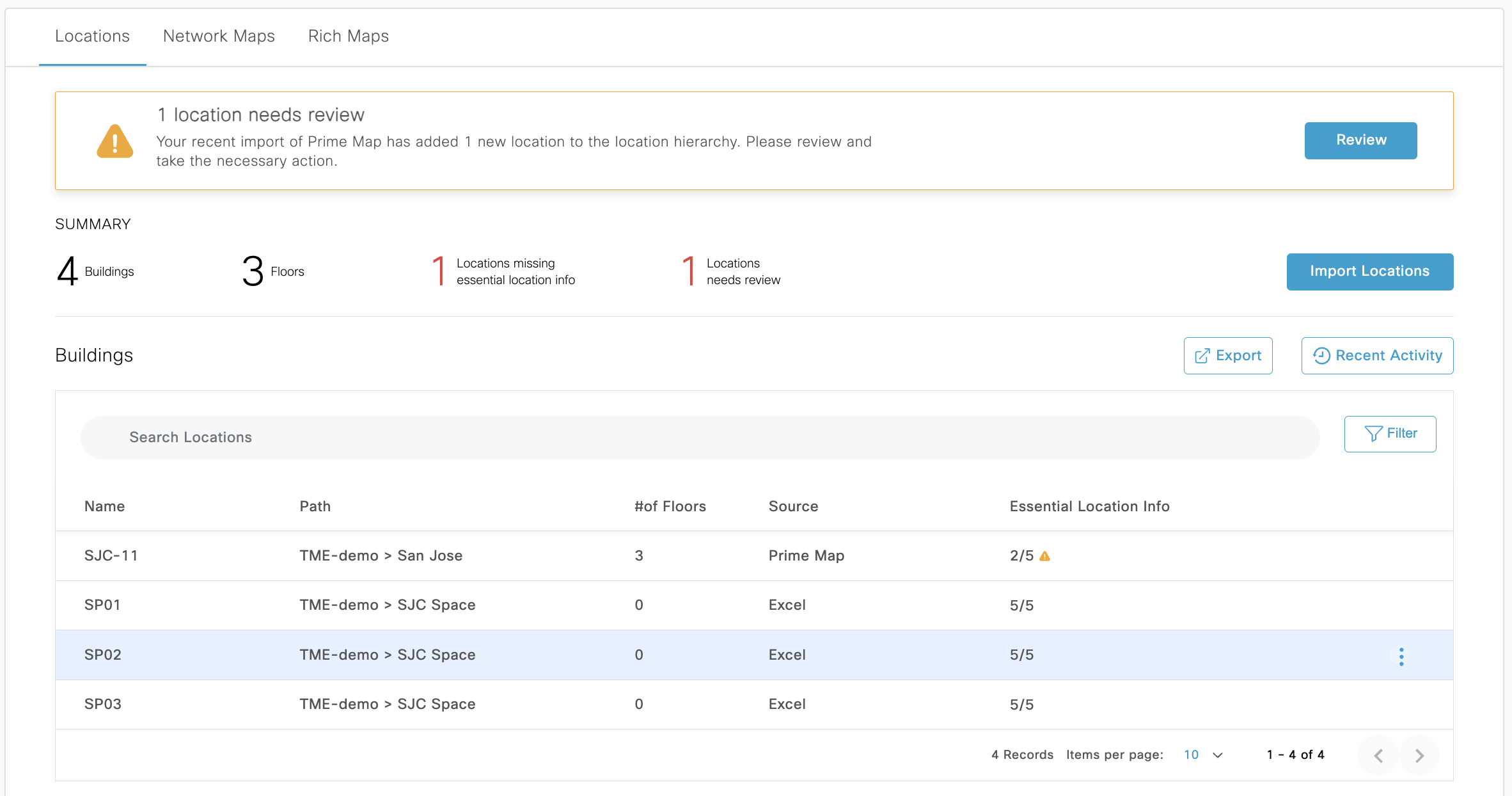
Choose ‘merge with’ to merge same location hierarchies that would have been previously created through Excel sheet upload, DNAC sync, etc. Remember to merge floors, too.
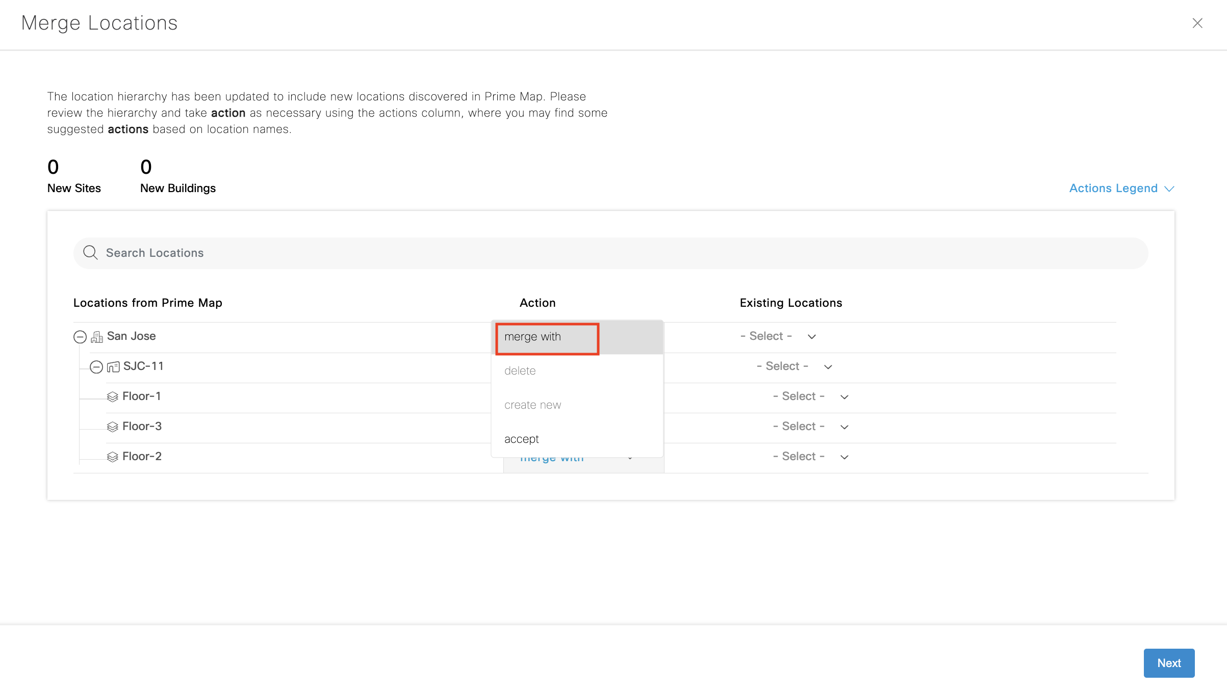
Choose the location that needs to be merged from the dropdown under Existing Locations.
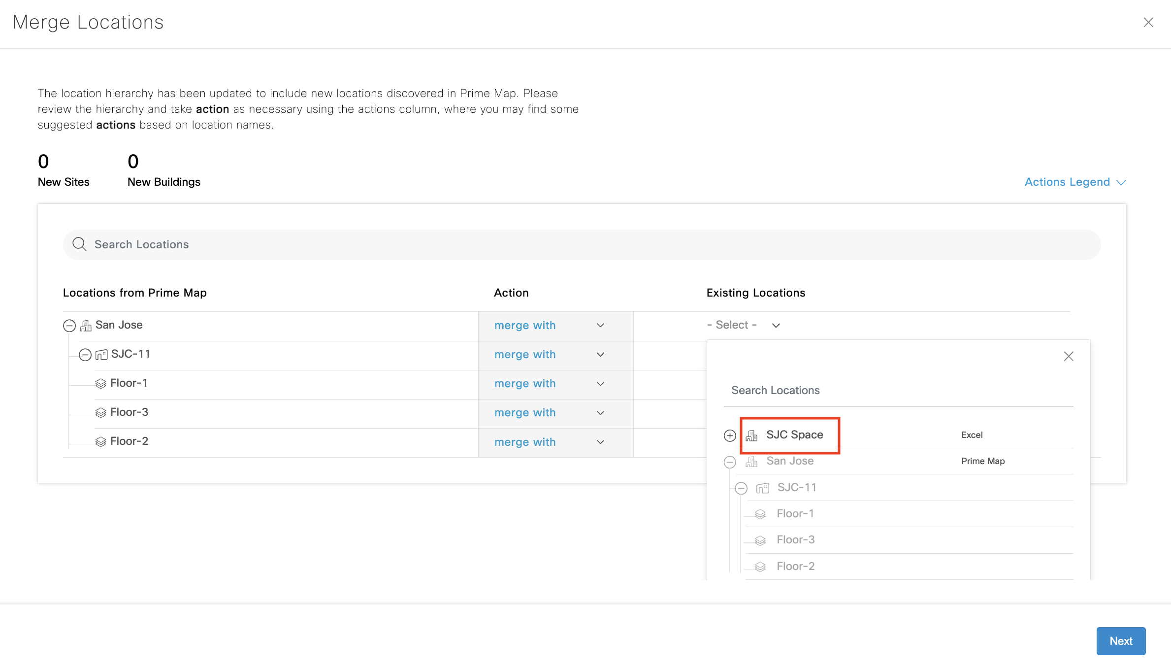
Once this is done the buildings get automatically merged as well.
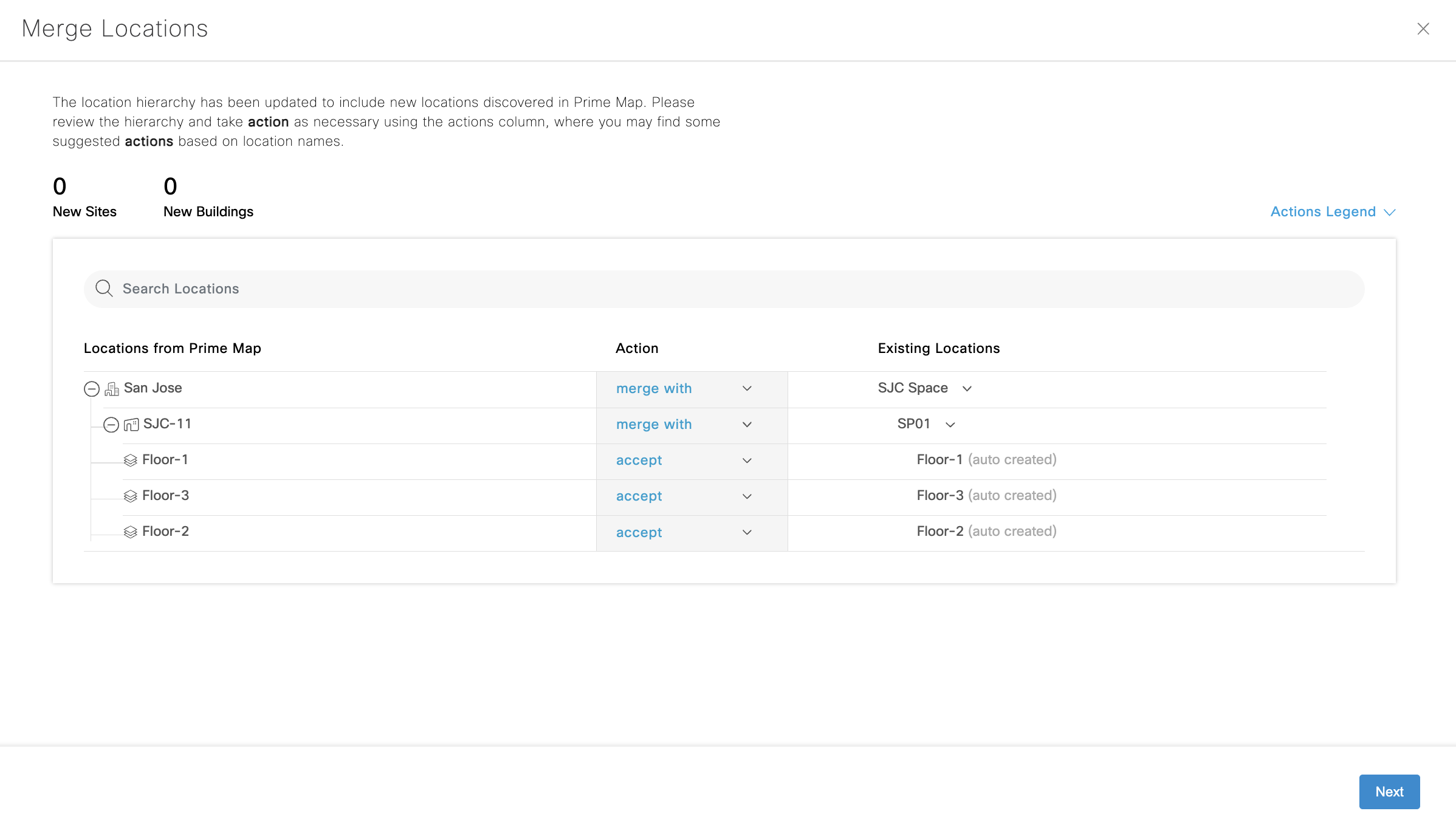
Once the Location Hierarchy is created, merged, and unified across multiple sources, the next step is to upload CAD files (.dwg) or Vector PDFs to generate a Cisco Spaces Digital Map.
Note: After uploading it can take up to 1 week for processing workspaces / office floorplans. Very large buildings and other maps (e.g. venues, retail, healthcare, education, manufacturing, etc.) can take longer, such as 3-4 weeks.
Under Setup > Locations & Maps
Click on the “Digital Maps” tab. Either search or choose the location of your desired building and Click on “Add Digital Map”.
Provide and confirm the correct building street address using Google address autocomplete.
(Note: click in the street address field and select the correct address from the dropdown for the best results)
Verify if the location pin is on the right address, if not, you can drag and drop the pin on the center or the focus area of the building. This will be the default center or focus area in other Spaces apps. Click on “Confirm Address”. Locations with an incorrect street address (must match the physical building outline) will be rejected.

Create floors by Clicking on “Add new floor”.
Note: Floors created or merged from Catalyst Center, Prime, Meraki, or Webex Control Hub may already be populated on this page.

Add missing metadata to the floors. Enter floor details and level number. Ensure that all floors are accurately listed with corresponding level numbers and short names as it cannot be modified without re-uploading files later.
Note: The same “Level Number” cannot exist in the same building. Floors must either be combined or split up at the source (e.g. Webex Control Hub, Catalyst Center, Meraki Dashboard). This metadata has a significant impact on apps such as Wayfinding, Signage, etc.
Upload CAD files or Vector PDFs by clicking on “Upload”
CAD files can be bundled into a ZIP file and uploaded at a building level using the “Bulk Upload” option or on a floor-by-floor basis with individual file upload per floor. Floorplans files must contain a single floor per file. Multipage vector PDFs and CAD files with multiple floor drawings will be rejected.
Uploading CAD file best practices

Note: Hidden and “frozen” layers will not be processed. Missing objects will need to be un-hidden or un-frozen, and re-uploaded to be processed correctly. Cross Reference (XREF) files are not supported.
Confirm Uploads. Choose “Map” from the dropdown and Click “Submit”.


Digital Map is now successfully submitted for processing. Click “Got it”.

Note: After uploading it can take up to 1 week for processing and QA for workspaces / office floorplans. Very large buildings and other maps (e.g. venues, retail, healthcare, education, manufacturing, etc.) can take longer, such as 3-4 weeks.
After successful upload the Processing Status changes to ‘processing’.

Once processed, Processing Status changes to ‘review pending’. Click on “Review” to view unpublished Digital Maps.
Add/Edit Room Labels. Once everything looks good, select “Publish this building”

You can also View/Edit once the Digital Map is published.
After publishing once, any further edits to the Digital Map, go into a ‘Draft’ state. Click “Publish this building” again and all draft edits reflect on digital signage and other apps immediately.
You can create zones on a specific floor map to get granular data in Cisco Spaces applications. These zones are defined in the Location Hierarchy, and can be used to display data in Right Now, Behaviour Metrics, Location Analytics etc.
Log in to Cisco Spaces dashboard
In the Cisco Spaces dashboard, click the Menu icon ![]() and choose Location Hierarchy.
and choose Location Hierarchy.
Under the Map tab, the 3D floor map is displayed. Select 2D map on the right panel
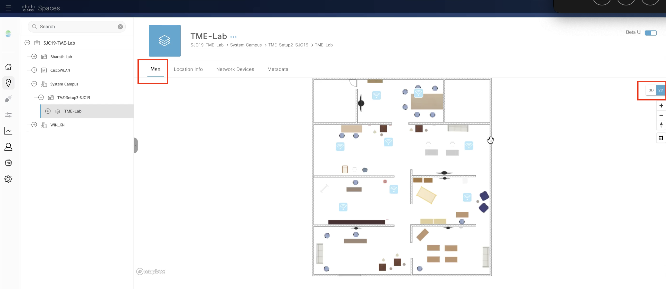
Click the Polygon tool ![]() on the map. The cursor changes to a plus icon.
on the map. The cursor changes to a plus icon.
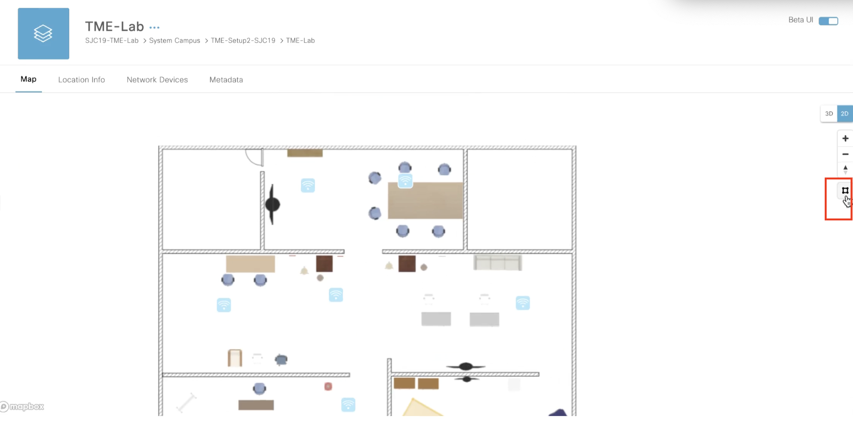
Click on the required map area and move the cursor to draw a polygonal zone of your choice.
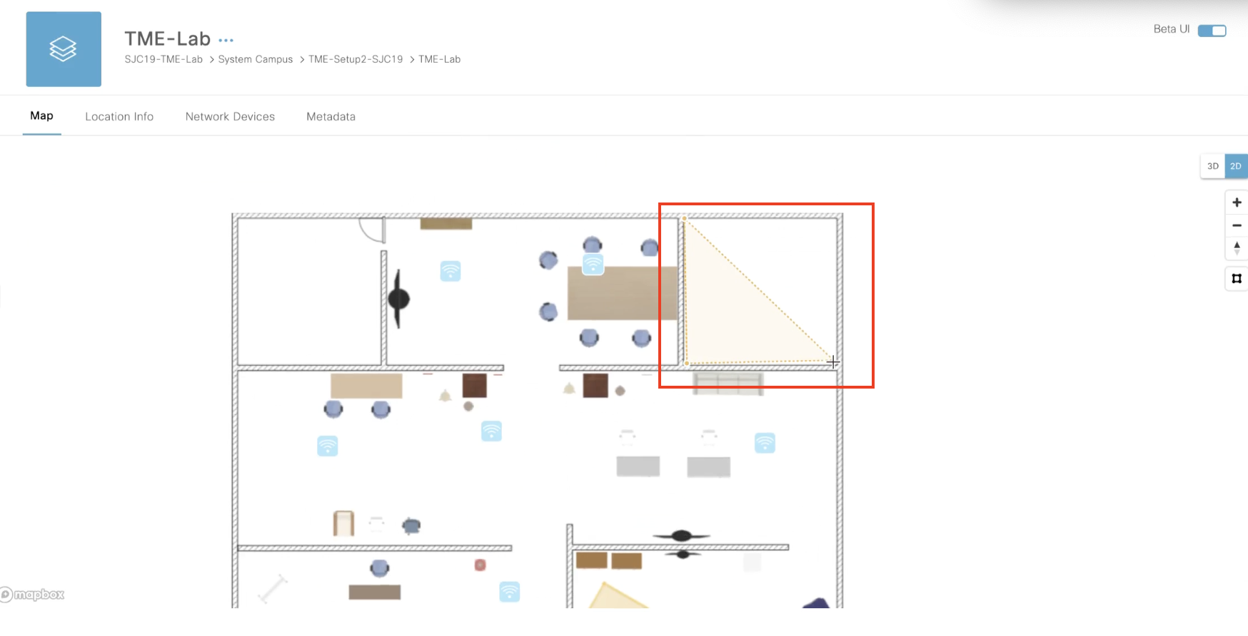
Double-click to complete the zone creation. A pop-up window is displayed on the right pane.
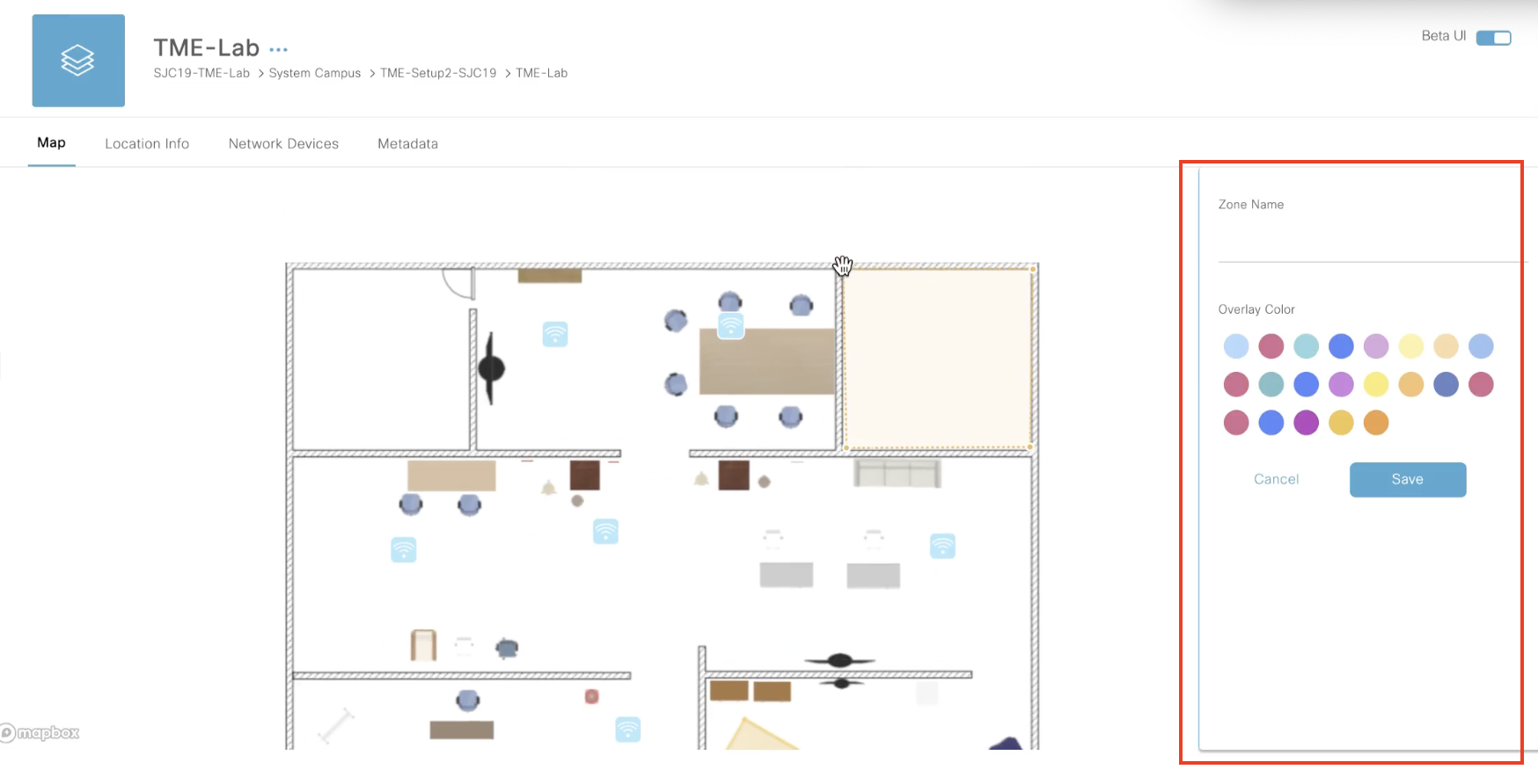
Select the overlay colour to distinguish the zone.
Click Save.
Note: These zones will then show up in the Location Hierarchy, and can be used to display data in Right Now, Behaviour Metrics, Location Analytics etc.
(Optional) To update the zone details, Click the polygon icon ![]() on the map.
on the map.
